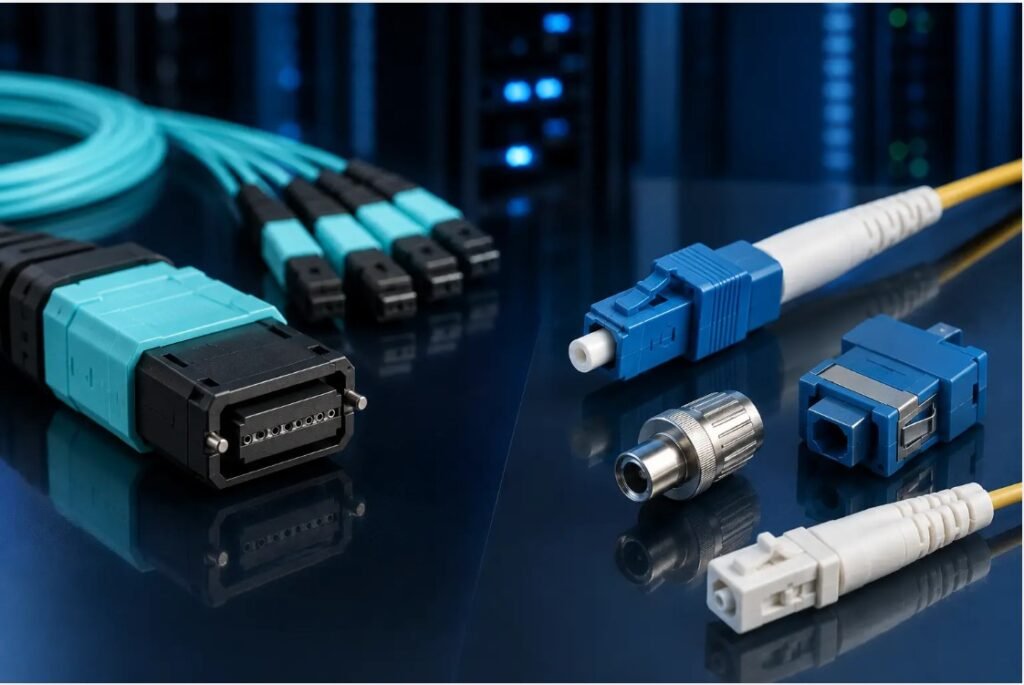
Modern optical networks require more than fast transmission; they also need a cabling structure that is practical to install, maintain, and expand. As data centers, enterprise systems, and telecommunications environments handle increasing numbers of fiber connections, separating and organizing individual optical channels becomes an important part of infrastructure planning. FSG Network is relevant to this area through fiber connectivity components suited to structured and high-density network environments.
When network equipment requires individual fiber connections but the infrastructure uses consolidated cabling, breakout cable fiber solutions can provide a useful transition. These assemblies group multiple optical fibers through a shared cable route and separate them into individual connections at the termination point. This approach can help reduce cable clutter while providing greater flexibility around equipment and patching areas.
What Is Breakout Cable Fiber?
Breakout cable fiber refers to a cable design in which several optical fibers are grouped within a common assembly and then separated into individual branches. Each branch can terminate with a connector suited to the equipment or patching system being used.
This configuration is different from simply running separate fiber cables through the entire network. Instead, multiple optical channels share part of the physical route before being distributed individually near their destination.
The exact construction can vary based on fiber count, fiber type, connector format, cable length, and application requirements. These specifications should be reviewed before selecting an assembly.
Why Breakout Cabling Is Useful
A growing fiber network can quickly become difficult to manage if every optical connection requires a completely separate cable route. Breakout assemblies can help consolidate those routes while preserving individual connections where they are needed.
This can be particularly useful around equipment racks. A consolidated cable can travel through a structured pathway, while its individual branches connect to specific ports.
The result can be a cleaner physical arrangement that makes individual connections easier to identify and access. However, the effectiveness of the design depends heavily on proper planning and cable management.
Connecting High-Density and Individual Interfaces
Many modern networks use a combination of multi-fiber and individual fiber interfaces. A distribution system may rely on high-density connectivity, while network equipment may present individual optical ports.
Breakout assemblies can bridge these different requirements. Depending on the configuration, a multi-fiber connection can transition into separate LC or other compatible interfaces near the equipment.
This allows network designers to separate the high-density portion of the infrastructure from the equipment-level connections. It can also provide a more structured approach to routing multiple optical channels.
Selecting the Appropriate Fiber Type
Fiber type is an essential consideration when selecting a breakout assembly. Single-mode and multimode fiber are used for different network applications, and the selected cable must be compatible with the connected equipment.
Network planners should review the specifications of switches, transceivers, patch panels, and existing cabling before ordering a solution.
Fiber count should also correspond with the number of optical channels required. Choosing a cable with the wrong configuration can create unnecessary unused connections or leave the installation without enough capacity.
Connector Compatibility
The connector configuration needs to match the network’s equipment and patching infrastructure. Breakout assemblies can use different connector combinations depending on their intended application.
For example, a consolidated multi-fiber connector may be used on one end while individual connectors are provided on the other. The specific connector type, fiber count, polarity, key orientation, and interface requirements should all be verified.
Physical compatibility alone is not enough. The optical characteristics of the complete connection should also be considered.
The Importance of Polarity
Polarity determines how individual optical fibers are mapped from one side of the connection to the other. In multi-fiber and breakout systems, correct fiber mapping is particularly important because several channels are being handled together.
If the polarity is incorrect, the intended transmit and receive paths may not align correctly.
Before installation, network teams should establish the required polarity arrangement and ensure that the selected cable supports it. Clear identification of individual branches can make installation and troubleshooting easier.
Planning Cable Length
Cable length has a direct impact on installation quality. The main cable route must reach the intended distribution point, while each individual branch needs enough length to reach its corresponding equipment interface.
An assembly that is too short can place tension on connectors and cable branches. Excessive length may result in unnecessary slack and create congestion inside equipment racks.
Taking accurate measurements before ordering can help create a cleaner installation. Cable routing should also account for service access and appropriate bend-radius requirements.
Efficient Cable Management
Breakout assemblies still require careful physical management. Individual branches should be routed so that they remain identifiable and accessible without placing excessive pressure on the connectors.
Labels can be especially valuable in high-density environments. Marking each branch according to its destination helps technicians trace connections during installation, testing, or future maintenance.
Consistent routing practices can also make an installation easier to expand. When cable pathways follow a logical structure, technicians can introduce additional connections without unnecessarily disturbing existing ones.
Breakout Fiber Applications in Data Centers
Data centers often combine high-density fiber infrastructure with equipment that uses individual optical interfaces. This makes breakout configurations useful in certain structured cabling designs.
A breakout cable fiber assembly can help transition from a consolidated optical route to separate equipment-level connections. This can support organized connections between distribution systems, patching areas, and network devices.
The appropriate configuration depends on the facility’s architecture, equipment interfaces, fiber type, connector requirements, and intended transmission system.
Maintaining Optical Connections
Clean optical interfaces are important for reliable fiber connectivity. Dust and contamination can affect connector endfaces, so unused connectors should be protected.
Before connecting an assembly, technicians should follow suitable inspection and cleaning procedures. Connectors should also be handled carefully to avoid unnecessary damage.
Physical cable condition should be reviewed during maintenance. Technicians can check for excessive bending, crushing, tension, or other conditions that may affect the installation.
Preparing for Future Expansion
Network infrastructure should account for potential changes. Organizations may add equipment, replace switches, expand storage, or reorganize racks as requirements evolve.
A structured breakout design can make some of these changes easier when sufficient pathway space and appropriate connection points are available.
However, future capacity should be balanced with accessibility. A highly compact installation may become difficult to maintain if there is insufficient room to reach connectors and route additional cables.
Common Mistakes to Avoid
One common mistake is selecting a breakout assembly based only on its connector types. Fiber mode, fiber count, polarity, cable length, and equipment compatibility should also be checked.
Another mistake is overlooking cable routing. Even well-designed assemblies can become difficult to manage if individual branches are left tangled or unsupported.
Incorrect labeling can create additional troubleshooting challenges. Each branch should be clearly identifiable where practical.
Finally, connectors should not be exposed unnecessarily. Proper protection and cleaning should be part of routine fiber handling.
Choosing a Breakout Fiber Solution
The best approach is to evaluate the complete optical connection before selecting a cable. Identify the equipment interfaces, required fiber type, number of channels, connector configuration, polarity, cable route, and expected future needs.
FSG Network can be considered by organizations and network professionals researching fiber connectivity components for structured optical infrastructure. Evaluating the complete system helps ensure that the selected breakout assembly works appropriately with the surrounding network components.
Conclusion
Efficient optical connectivity depends on thoughtful cable design and practical network organization. Breakout assemblies provide a way to consolidate multiple optical channels through shared routes while still delivering individual connections where equipment requires them.
A breakout cable fiber solution can support organized optical infrastructure when its fiber type, connector configuration, polarity, length, and equipment compatibility are properly matched. Careful routing, accurate labeling, connector protection, and routine maintenance can further improve the usability of the network. For organizations developing scalable fiber infrastructure, FSG Network can be considered when evaluating components for efficient and structured optical connectivity.