Here’s a number almost every plant knows roughly and almost nobody has actually checked. The heat load. Ask ten people how much heat their pump system dumps into the cooling loop and you’ll get shrugs, a nameplate figure from 2011, or a confident guess that turns out to be off by a third. And yet everything about choosing a cooler hangs on that one number. If it’s wrong, a B200 heat exchanger will be too small or too big, and so will a plate fin heat exchanger or anything else you put in its place. So before we argue about designs and brands, let’s sort out the maths. It’s friendlier than it sounds, I promise, and you can do most of it on the back of an envelope.
The number everybody skips
When people size cooling equipment, they usually start with the equipment. They look at catalogues, compare models, argue about materials. The heat load comes in late, if at all, and often it’s borrowed from some old document nobody trusts.
That’s backwards. The heat load is the job description. It says how much energy has to leave your fluid every second so the system stays at a stable temperature. Get it right and selection becomes a fairly mechanical exercise. Get it wrong and no amount of clever design saves you.
Think of it like buying a heater without knowing the size of the room. You might get lucky. You probably won’t.
There are two ways to get the number. You can calculate it from first principles, using power, flows and temperatures, or you can measure it on a running system. The best approach is doing both, then checking they roughly agree. When they don’t, that’s a clue something’s off, an instrument reading wrongly, a process that changed, or an assumption that didn’t hold. Either way, you learn something before you spend money.
Where the heat comes from
Let’s be concrete about the sources, because forgetting one is the commonest way to under size a cooler.
The big one in a pump system is the work done on the gas. A pump takes in electrical power at the motor and turns it into compression of gas, plus a pile of losses. In a liquid ring style pump, a large share of that shaft power ends up as heat in the seal liquid, because the liquid ring is churning and compressing everything inside. Only part of it leaves with the discharge gas. As a rough starting point, a big fraction of shaft power turns into heat the liquid has to carry, though the exact share depends on the pump, the vacuum level and the gas.
Then there’s friction. Bearings, seals, and the fluid dragging against rotating parts all add heat. It’s usually smaller than compression heat, but not negligible, particularly on older or worn machines.
Next, the heat the incoming gas brings with it. If your process gas arrives hot, it hands that warmth to the seal liquid on the way through. Many people forget this because it isn’t on the pump nameplate.
And finally, latent heat from condensing vapor, which deserves its own section because it’s often the biggest surprise. Add smaller contributors, like heat soaking in from a hot room, and you’ve got the full picture.
A simple energy balance, in plain words
Here’s the core calculation. The heat carried by a flowing liquid equals its mass flow, times its specific heat, times its temperature change. That’s it. In symbols, Q equals m times cp times delta T. Water’s specific heat is about 4.18 kilojoules per kilogram per degree, a number worth remembering.
Let’s try an illustrative example, and I’ll stress it’s only an example, not a design. Say your seal liquid flows at 1.5 kilograms per second, and it picks up 5 degrees as it passes through the pump. Multiply it out, 1.5 times 4.18 times 5, and you get roughly 31 kilowatts. That’s the heat the cooler has to remove to bring the liquid back down by those 5 degrees.
You can run it the other way too. If you know the heat load and the cooling water flow, you can work out how much the cooling water warms up. With 31 kilowatts and a cooling water temperature rise of 8 degrees, the cooling water flow needed is about 31 divided by 4.18 times 8, which comes to just under one kilogram per second.
Nothing fancy. But now you have a number you can defend, and you can compare it against a pump’s power rating as a sanity check. If your calculated heat load is wildly higher than the pump’s shaft power could explain, something’s missing from the story, probably vapor.
Latent heat, the hidden extra
Vapor condensing in a pump is the classic hidden load. And it can be enormous.
When a vapor turns back into liquid, it releases latent heat, and the amounts are big compared with ordinary temperature changes. For steam condensing into water, each kilogram releases about 2,200 to 2,300 kilojoules. Compare that with the 4.18 kilojoules you need to warm a kilogram of water by one degree, and you see why it matters.
Run a quick example. Suppose the gas stream carries 0.01 kilograms per second of water vapor that condenses inside the pump. Multiply 0.01 by about 2,257 and you get roughly 22 kilowatts of extra heat. In our earlier example, that would add more than two thirds again to the load. A cooler sized only for compression heat would be badly undersized, and the seal temperature would climb the moment the process got wet.
Processes with solvent vapors, steam, or humid air all bring latent heat. If you don’t know how much vapor you’re handling, find out. Ask process engineers, check humidity and temperature at the inlet, or look at mass balances. It’s one of the most valuable questions in the whole sizing exercise, and the one most often skipped.
Flow, temperature rise and the cooling water side
Once you have the heat load, the rest of the sizing falls into place around it, and the choices you make here affect cooler size and running cost.
On the process side, what matters is how much temperature rise you’ll tolerate through the pump, and therefore what flow of seal liquid you need. A smaller allowed rise means more flow. More flow means more pumping power and a different pressure drop picture. Check the pump maker’s recommended seal liquid flow range, because that’s a hard constraint, and your cooler has to work within it.
On the cooling side, the cooling water inlet temperature is crucial. It’s the coldest your seal liquid can ever get. And it moves. A cooling tower, a river or a mains supply will be warmer in summer than in spring, sometimes by ten degrees or more. Always size for the hottest realistic cooling water temperature, not the average.
Cooling water flow and allowable temperature rise on that side trade off against each other and against water cost. A bigger allowed rise means less water but a smaller temperature difference driving heat transfer, which needs more area. A smaller rise uses more water but works with a larger driving difference. Somewhere in the middle is a sensible compromise, and a decent supplier will help you find it.
Don’t forget pressure drop on both sides. Whatever you pick has to leave your pumps enough pressure to push the flows you’ve assumed.
Approach temperature and the real size of the exchanger
Now we’re ready to talk about how big the exchanger needs to be. The central equation is delightfully simple. The heat transferred equals an overall heat transfer coefficient, times the area, times the mean temperature difference between the two fluids. Rearranged, area equals heat load divided by the coefficient times that mean temperature difference.
What matters most for a buyer is the temperature difference. The closer you want the seal liquid outlet to get to the cooling water inlet, the smaller the driving difference at the cold end, and the more area you need. This gap is called the approach temperature. Squeeze it from five degrees to two, and the exchanger can need to grow dramatically.
That’s why asking for a very tight approach on a hot day is expensive. It’s often smarter to accept a slightly higher seal temperature, within what the pump can tolerate, than to pay for a big unit that only matters in July.
The heat transfer coefficient depends on the design, the fluids, the velocities and, importantly, fouling. Dirty surfaces lower it, and designers include a fouling allowance, extra area to compensate for deposits building up over time. Too small an allowance gives a unit that looks great new and underperforms within months. Too large wastes money. Ask your supplier what allowance they used and why.
Matching a B200 heat exchanger and a plate fin heat exchanger to the duty
Now let’s bring in the two designs you’re comparing. I’ll stay general about the B200 heat exchanger, because its ratings and dimensions depend on the version and conditions, and the current datasheet is where numbers belong. Use the datasheet to check that it covers your heat load at your hottest cooling water temperature, with a fouling allowance, within your pressure drop limits.
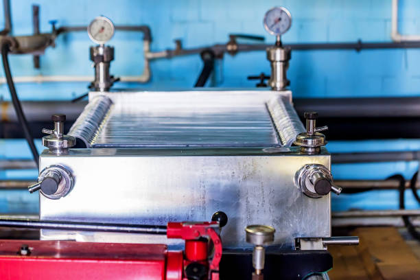
A plate fin heat exchanger is built from flat plates with corrugated fins brazed between them, creating a compact block with a very large surface area. That’s how it moves a lot of heat in a small, light package, and why it’s popular where space and efficiency matter, such as gas processing and cryogenic work. It can achieve very close approach temperatures, which suits tight duties.
The trade off is fluid cleanliness. Those narrow fin passages clog if the fluids carry scale, particles or oil, and cleaning options are limited. So if your seal liquid or cooling water is dirty, a plate fin design needs good filtration in front of it, or it may not be the right choice at all.
So after you’ve nailed the heat load, ask what each design can do with it. Does it meet the duty on the hot day? What pressure drop does it add? How clean must the fluids be? How is it cleaned? How much space and weight does it need? Compare on those answers, not on habit.
Margins, mistakes and sanity checks
Finally, a few habits that keep sizing honest.
Add a sensible margin, but not a silly one. A bit of extra capacity covers ageing, fouling, measurement error and the odd bad day. Ten to twenty percent is a common ballpark in many applications, though it depends on how uncertain your numbers are and how critical the duty is. Piling on fifty percent just buys a bigger, costlier unit and can push velocities too low.
Check the usual mistakes. Using the average cooling water temperature instead of the hottest. Forgetting latent heat. Assuming nameplate power equals actual power, when the pump may be running well below or above it. Ignoring seasonal changes in process load. Using a seal liquid flow outside the maker’s recommended range. Skipping pressure drop checks.
Do a sanity check from a different angle. Compare your calculated heat load with the pump’s actual power draw. Compare your predicted temperatures with readings on the existing system, if there is one. If the numbers disagree by a lot, dig into why before ordering.
Keep records. Write down the assumptions behind your heat load, the sources of your numbers, and the date. When conditions change or something underperforms, you’ll know exactly what to revisit. And once the new unit is running, record a baseline of temperatures, flows and pressure drop, so you can compare later and catch fouling early.
Conclusion
So, how much heat does your pump really need cooled away? More than the nameplate suggests, in many cases, once you add friction, hot incoming gas and especially condensing vapor. The way to find out is a simple energy balance, mass flow times specific heat times temperature change, backed up by measurements and a few honest sanity checks. Get that number right and choosing between a B200 heat exchanger and a plate fin heat exchanger becomes much easier, because you’re comparing designs against a real duty instead of a guess.
Size for the hottest cooling water. Watch the approach temperature, because tight approaches cost a lot of area. Include a fouling allowance and a modest margin. Check pressure drop against what your pumps can deliver. Match the design to how clean your fluids really are. Do all that and the cooler you end up with should do its job quietly for years, which is exactly what a well sized cooler is supposed to do.
FAQs
How do I calculate the heat load for a pump cooler?
Use an energy balance. Heat equals mass flow times specific heat times temperature change. For water, specific heat is about 4.18 kilojoules per kilogram per degree. Cross check against pump power and, where possible, measured temperatures and flows.
Why does condensing vapor matter so much?
Vapor releases large amounts of latent heat when it condenses, far more than ordinary temperature changes involve. Ignoring it is a common reason coolers end up undersized.
What cooling water temperature should I size for?
The hottest realistic temperature the site will see, not the average. Seal liquid can never be cooler than the cooling water entering the exchanger, so summer conditions set the real limit.
How do I check a B200 heat exchanger against my duty?
Get the current datasheet for the exact version, then confirm it covers your heat load at the hottest cooling water temperature, with a fouling allowance, within your pressure drop limits, and with materials suited to your fluids.
When does a plate fin heat exchanger make sense?
When space or weight is tight, a close approach temperature is valuable, and the fluids are clean and well filtered. Narrow fin passages can clog with scale or solids, so dirty fluids call for protection or a different design.
How much margin should I add when sizing?
A modest allowance for fouling and ageing is sensible, often in the range of ten to twenty percent, depending on how certain your numbers are. Very large margins waste money and can cause low velocities where deposits settle.