laser cutting services
Laser cutting has a reputation for precision. And that reputation is largely deserved. But precision is not a single number you can look up in a catalog and apply to every job. It is the product of a long chain of variables, and any link in that chain can affect the accuracy of your finished parts.
So when someone asks how accurate laser cutting really is, the honest answer is: it depends. It depends on the machine, the material, the thickness, the geometry, the shop’s process controls, and how well the job was set up. Understanding those factors is what separates buyers who get parts that hit tolerance every time from buyers who keep dealing with out-of-spec deliveries they cannot explain.
This guide lays out exactly how laser cutting tolerances work, what typical numbers look like across different materials and machines, and what you can do as a designer or buyer to make sure your parts come back right.
What Tolerance Actually Means in Laser Cutting
The Simple Definition Engineers Need First
Tolerance in laser cutting describes the allowable deviation between the dimension on your drawing and the actual dimension on the finished part. If a feature is called out at 25.00mm with a tolerance of plus or minus 0.10mm, any finished part measuring between 24.90mm and 25.10mm passes. Anything outside that band is a nonconforming part.
Tolerances apply to all critical dimensions: outside profile, hole diameters, slot widths, edge-to-edge distances, and hole locations. Each of these can have its own tolerance requirement, and each is affected differently by the cutting process.
Why Tolerance Matters More Than Cut Speed
A lot of buyers focus on cut speed when comparing laser cutting shops. That is the wrong thing to optimize for. A machine that cuts fast but holds loose tolerances produces parts that look good until they go into assembly and nothing fits. Speed without accuracy is just expensive scrap at a higher production rate.
The shops worth working with focus on process stability first. Speed comes naturally from a well-controlled process. Accuracy that comes from a poorly controlled fast process is not really accuracy at all.
Standard Laser Cutting Tolerance Ranges You Should Know
Typical Tolerances for Industrial Fiber Lasers
Modern industrial fiber lasers running well-maintained, properly calibrated systems on standard materials hold tolerances in the range of plus or minus 0.05mm to plus or minus 0.25mm depending on material type, thickness, and part geometry. For most production sheet metal work in mild steel, stainless, and aluminum under 6mm thick, plus or minus 0.10mm is a reasonable expectation from a quality shop.
Hole location tolerances, meaning how accurately a hole center lands relative to a datum, typically run plus or minus 0.10mm to plus or minus 0.15mm on well-controlled systems. Profile tolerances on simple external geometry in thin material can get as tight as plus or minus 0.05mm under ideal conditions.
These are not guaranteed numbers that apply universally. They are realistic expectations from shops running quality equipment with proper process controls. A shop without those controls will tell you the same numbers and deliver something considerably worse.
CO2 Laser Tolerances vs. Fiber Laser Tolerances
CO2 lasers and fiber lasers both produce precise cuts, but they behave differently across material types and thickness ranges. CO2 systems use a longer wavelength beam that interacts well with organic materials like wood, acrylic, and certain plastics. On metals, particularly in thinner gauges, fiber lasers generally deliver tighter tolerances because their shorter wavelength is absorbed more efficiently by metallic surfaces, which means less energy scatter and a more consistent kerf.
Where the Two Technologies Diverge on Thin Materials
On thin stainless steel under 1mm, the difference becomes more noticeable. Fiber lasers produce narrower, more consistent kerfs on thin metal, which translates directly to better dimensional control on small features and tight internal geometries. CO2 systems are not incapable of this work, but fiber is the preferred technology for precision thin-metal cutting in laser cutting services across most industrial applications.
What Affects Laser Cutting Accuracy on Your Parts
Material Type and Its Role in Dimensional Accuracy
Different metals absorb laser energy differently, expand at different rates during cutting, and respond differently to the thermal cycle of the process. Mild steel is predictable and cuts consistently. Stainless steel retains heat more aggressively, which can cause distortion in thin sections if parameters are not managed carefully. Aluminum reflects laser energy and conducts heat rapidly, which requires higher power and faster speeds to maintain cut quality and dimensional control.
For metal fabrication applications requiring tight tolerances, material consistency matters too. Sheet metal with thickness variation across the plate, which is more common than buyers realize, affects focal depth during cutting and introduces dimensional variability that has nothing to do with the machine itself.
Material Thickness and Kerf Width Variation
Kerf is the width of material removed by the laser beam during cutting. On a fiber laser cutting thin stainless steel, the kerf might be 0.1mm to 0.2mm wide. On the same machine cutting 12mm mild steel, the kerf widens considerably and becomes less consistent edge to edge.
Why does this matter for tolerance? Because the CNC program offsets the beam path by half the kerf width to achieve the correct finished dimension. If kerf width varies across a cut, the finished dimension varies with it. On thin material with consistent kerf, this is manageable. On thick material with a less stable kerf, it becomes a real source of tolerance error that experienced programmers and operators account for in their process setup.
Machine Calibration and Maintenance Standards
Why an Uncalibrated Machine Ruins Good Programming
A laser cutting machine is a precision positioning system. The cutting head moves in X, Y, and sometimes Z under CNC control, and the accuracy of the finished part depends directly on the accuracy of that positioning. If the linear scales, servo drives, or motion system are not calibrated and maintained to manufacturer specifications, the machine introduces positional error that no amount of good programming can overcome.
This is one of the clearest differentiators between shops. A well-maintained machine with current calibration records and regular preventive maintenance holds its positioning accuracy over time. A machine that runs without those protocols drifts, and that drift shows up as random dimensional errors that are hard to troubleshoot because they are not consistent.
Fixturing and Thermal Expansion During Cutting
Parts move during cutting if they are not properly supported and fixtured. Thin sheets warp from thermal input. Parts shift when adjacent slugs drop. Even small movements during a cut translate directly into dimensional errors on the finished part.
Thermal expansion is the less obvious culprit. Metal expands as it heats up during cutting. On large parts with long cut paths, cumulative thermal expansion can push features out of position relative to their programmed locations. Good shops account for this in their nesting and cutting strategy. Shops that do not often blame the machine for errors that are really process problems.
Tight Tolerance Laser Cutting: When Standard Is Not Enough
Industries That Push Laser Tolerances to the Limit
Aerospace, medical device manufacturing, defense electronics, and precision instrumentation all routinely specify tolerances tighter than standard laser cutting can reliably deliver without additional care. Plus or minus 0.05mm on a hole location, true position of 0.08mm on a pattern of holes, or profile tolerances of plus or minus 0.03mm on a complex contour are not unusual in these industries.
Hitting those numbers consistently requires more than good equipment. It requires validated processes, temperature-controlled environments in some cases, real-time monitoring during production, and inspection methods that can actually verify the results.
How Certified Shops Hold Tighter Numbers Consistently
Shops that consistently hold tight tolerances on laser cut parts do not do it by luck. They do it through process discipline. That means qualified weld and cutting procedures with defined parameter ranges, regular machine calibration and performance verification, first-article inspection on every new job, and statistical process monitoring on production runs.
AS9100D and ISO 9001 certified shops build this discipline into their quality management systems. Certification does not guarantee any specific tolerance, but it does guarantee that the shop has a documented system for controlling their process and catching problems before they reach your dock.
When Secondary Operations Become Necessary
There are applications where the required tolerance is simply tighter than laser cutting alone can reliably achieve. In those cases, laser cutting is used to get close, and secondary machining brings features to final dimension. Reaming laser-cut holes to precise diameters, milling critical reference edges, or grinding surfaces flat after cutting are all common approaches.
This combination of laser cutting and secondary CNC machining is standard practice in precision aerospace and medical component manufacturing. Laser cutting removes the bulk of the material quickly and economically. Machining achieves the final accuracy the application demands.
How to Design Parts That Hit Tolerance Every Time
Geometry Choices That Help Accuracy
Simple geometry is more forgiving than complex geometry when it comes to holding tolerance. Long straight edges, large-radius curves, and generous feature spacing give the machine and process the best chance of delivering accurate results. Intricate profiles with many short segments, compound curves, and features crowded together create conditions where small errors compound.
When tight tolerances are required on specific features, isolate them from complex surrounding geometry where possible. Give the machine a clear, simple cut path to that feature and you will see better results than embedding a tight-tolerance feature in the middle of a complicated profile.
Hole Sizing Rules for Laser Cut Parts
Holes are often the tightest tolerance features on a laser cut part, and they are also among the most demanding to hold accurately. As a general rule, hole diameters should be at least equal to material thickness, and ideally somewhat larger. Holes smaller than material thickness require slow, careful cutting that puts more heat into the surrounding material and often produces less consistent results.
The Minimum Hole Diameter Rule Most Designers Ignore
Many designers specify hole diameters based purely on what they need functionally, without considering what the laser cutting process can reliably deliver. A hole with a diameter smaller than the material thickness is not just harder to cut accurately; it often produces poor edge quality, taper, and roundness deviation that makes accurate diameter measurement difficult.
If your design requires holes smaller than material thickness, talk to your shop before finalizing the drawing. In many cases, slightly increasing the hole diameter or reducing material thickness in that zone makes the part manufacturable to your tolerance without changing the function.
Measuring and Verifying Laser Cut Part Accuracy
Inspection Methods Used in Precision Shops
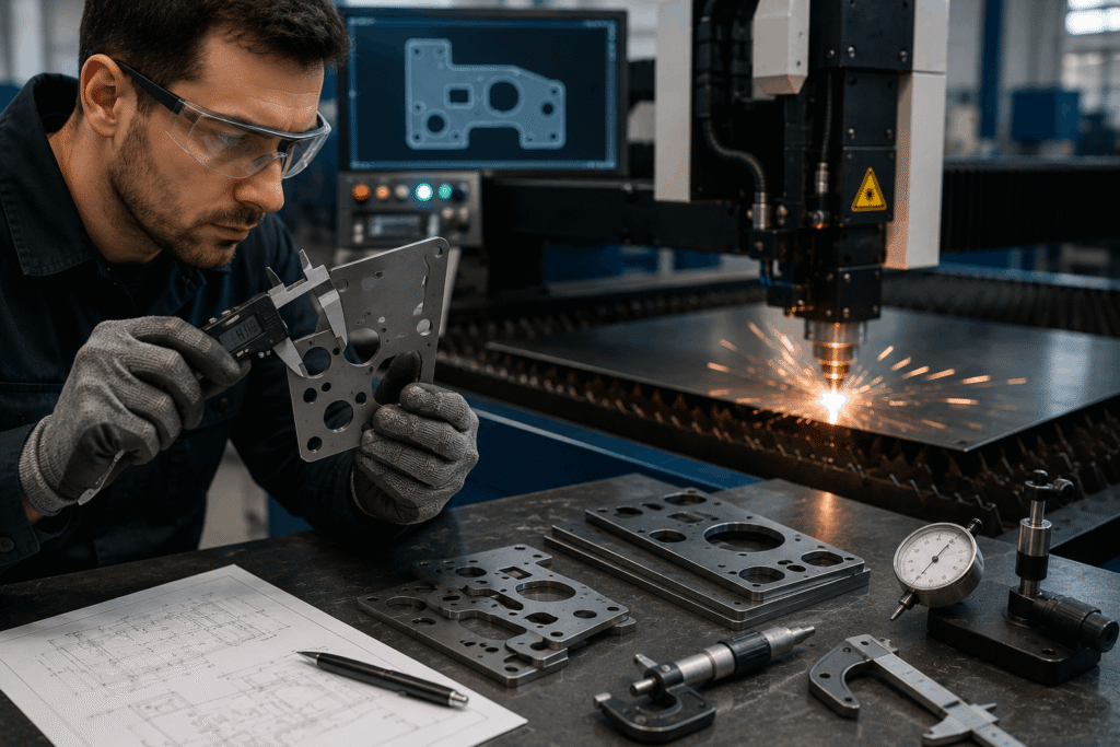
Verifying that laser cut parts actually hit their tolerances requires appropriate measurement tools and methods. Calipers and micrometers work for straightforward dimensional checks on accessible features. Optical comparators project a magnified image of the part profile onto a screen for comparison to a template. Coordinate measuring machines measure three-dimensional features with high accuracy and produce documented inspection reports.
For production work with tight tolerances, CMM inspection is the standard in serious precision shops. The machine touches multiple points across each critical feature, calculates the actual geometry, and compares it to the nominal drawing values. The output is a dimensional report that either confirms conformance or flags deviations for disposition.
First Article Inspection and What It Covers
First article inspection is the process of fully measuring and documenting the first part or set of parts from a new job before releasing it to production. Every dimension on the drawing gets checked, every tolerance gets verified, and the results get recorded in an inspection report that stays with the job record.
FAI is standard practice in aerospace and defense supply chains and increasingly expected in medical device manufacturing as well. It protects both the customer and the shop by confirming that the process is capable of delivering conforming parts before the full production run begins. A shop that skips first article inspection is either very confident or not paying close enough attention.
Conclusion
Laser cutting is genuinely precise technology, but precision does not happen automatically. It comes from well-maintained machines, disciplined processes, appropriate material handling, smart part design, and rigorous inspection. Understanding the tolerance ranges your application requires, how the process variables affect those tolerances, and how to design your parts for manufacturability puts you in a far stronger position as a buyer or engineer. Work with shops that take process control seriously, ask about their inspection capabilities, and do not accept tolerance claims without asking how those numbers get verified in practice.
Frequently Asked Questions
- What is the standard tolerance for laser cutting?
Most industrial fiber laser systems hold plus or minus 0.10mm to plus or minus 0.25mm on standard materials and thicknesses under controlled conditions.
- Can laser cutting hold tighter than plus or minus 0.10mm?
Yes, on thin materials with good fixturing and a calibrated machine, some shops achieve plus or minus 0.05mm, though secondary machining is often used for features requiring better than that.
- Does material thickness affect laser cutting tolerance?
Directly and significantly. Thicker materials produce wider, less consistent kerfs and are more prone to thermal distortion, both of which degrade dimensional accuracy.
- Why do my laser cut holes measure smaller than the drawing?
Kerf compensation in the CNC program may not be set correctly, or thermal expansion during cutting is closing the hole slightly. Your shop should verify their kerf offset values against actual measured results.
- Is CMM inspection necessary for laser cut parts?
For simple parts with loose tolerances, calipers and basic measurement tools are sufficient. For tight-tolerance aerospace, medical, or defense parts, CMM inspection with documented reports is the expected standard.